Kinetic Studies of Air Column
Acoustics
R.
Dean Ayers and Mark T. McLaughlin
Department of Physics and Astronomy, California State University Long
Beach, Long Beach, CA 90840-3901,
USA
The linear behavior of an air column can now be illustrated very easily using
a personal computer.
Concepts that may have been somewhat abstract become more concrete with
kinetic images on the computer screen.
One basic example is a representation of standing waves with imperfect
nodes in terms of several dependent variables, each of which displays a
“lurching” or “galloping” behavior.
Because of the emphasis that they receive in introductory courses,
undamped traveling waves and ideal standing waves can play too prominent a
role in a student’s understanding of realistic waves, which are subject to
damping in propagation and on reflection.
A detailed examination of the intermediate “lurching” waves may
help to relegate those idealized special cases to their proper roles as
limiting behaviors.
The treatment of the example presented here is analytic rather than
numerical, with the computer just providing kinetic images of the solutions.
The use of scrollbar controls for physical parameters of the wave
images encourages informal experimentation.
Allowing students to write their own program lines for the calculation
of dependent variables may help them to make the transition from using real
sinusoids to working with complex exponentials.
“LURCHING”
WAVE BEHAVIOR
Two undamped sinusoidal plane waves of the same
wavelength l
propagate in opposite directions in a uniform pipe. All acoustic pressures
are normalized to the amplitude of the stronger wave, which travels to the
right (+ x
direction). The amplitude of the
weaker wave is R, the pressure reflection coefficient at the origin, and here
R is limited to positive values. Thus
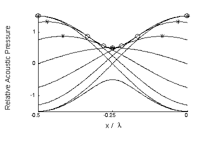
at time t = 0 both pressure waves have crests at x = 0. At each point in the region x < 0, where the waves
overlap, the total acoustic pressure varies sinusoidally in time.
The amplitude of that temporal variation is
Ap(x) = [1 + R2
+ 2Rcos(2kx)] 1/2,
(1)
where
the propagation number k = 2p
/ l.
Imperfect nodes and antinodes are visible in the amplitude envelope,
which is the pair of dotted curves ± A
p (x) in Fig. 1. (The
value R = 0.5 results from dividing the area of the pipe’s cross section by
three for
x >
0.)

FIGURE
1. Amplitude envelope (dotted) and lurching wave plots (solid)
for R = 0.5: V = crest;
O = contact point.
Each frame
in a moving picture of the total disturbance is a sinusoidal function of x.
A few of these are shown at an interval of Dt
= T / 12
from -T
/ 2 to
0, with T = the period. The
height of a crest in the total wave (
V)
must vary as it shifts in order to squeeze through each node.
The curve traced by a crest is
pcrest(x) =
(1 -
R2 ) /
[1 + R2 -
2Rcos(2kx)] 1/2.
(2)
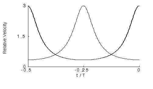
The
velocity of the total wave varies, whether one focuses on a crest or on a
point of contact with the upper envelope curve (temporal maximum, O). For either type of feature the average velocity over a half
period is v = l
/ T to the right. Within that
interval the variation can be considerable, as shown in Fig. 2.
Crests travel rapidly through nodal regions and slowly near antinodes,
while temporal maxima show the opposite behavior.
The two normalized velocities have the same time dependence except for
a shift by T/4:
vx, feature / v = (1 -
R2) / [1 + R2 ± 2Rcos(2w
t)],
(3)
with
+ for a crest, -
for a contact point, and w
= 2p
/ T.

FIGURE
2. Normalized feature velocities: solid = crest; dotted =
contact (temporal maximum).
The
behavior of the normalized particle velocity is similar to that of the acoustic
pressure. In this example its reflection coefficient at x = 0 is just -R,
so we can adapt the results obtained for pressure.
The amplitude envelope for x
< 0
gets shifted by l
/ 4,
placing a node at x =
0, and the signs for the two velocities in Eq. (3) are exchanged.
The antinodes and nodes of the two amplitude envelopes
are the only locations where acoustic pressure and particle velocity are in
phase with each other, as in a single traveling wave.
At those points the lurching wave can be coupled without reflection to an incident wave in an upstream pipe of
appropriate diameter. For the odd integer multiples of l
/
4 between a node and an antinode, the diameter of the lurching wave
segment must be the geometric mean of the diameters on either side of it to
avoid reflection. For the integer
multiples of l
/ 2
between two antinodes or two nodes, the diameters upstream and downstream from
the lurching wave segment must be equal.
ENERGY
AND INTENSITY
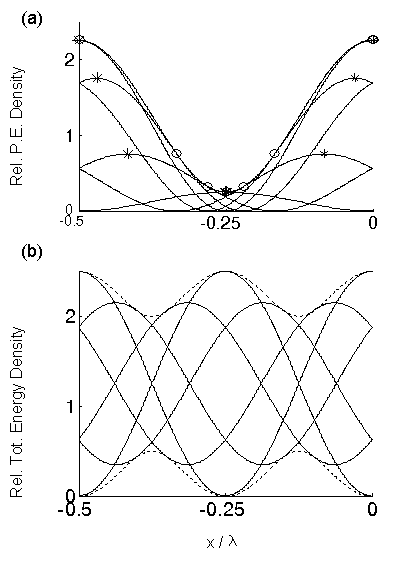
The potential and kinetic energy densities also show lurching behavior.
Their normalized
values are just the squares of the
normalized acoustic pressure and particle velocity, respectively. The potential
energy density and its envelope are shown in Fig. 3(a).
The kinetic energy density has the same envelope shape, but shifted by l
/ 4. The
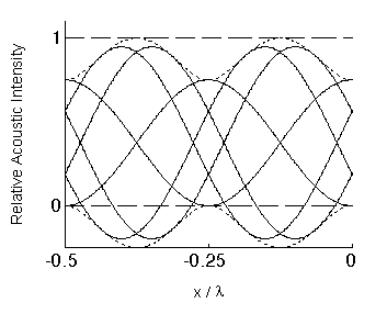
total energy density and its envelope are shown in Fig. 3(b). Finally, Fig. 4
shows the envelope and instantaneous plots for the acoustic intensity, pvx,particle,
the power flux per unit area. The horizontal lines at 0 and 1 are the upper
limits for the two envelope curves, independent of the value of R.

FIGURE
3. Lurching behaviors of energy densities and
their envelopes:
(a) potential energy density, (b)
total energy density; R = 0.5 and Dt
= T/12 for -T/2
< t < 0.
IMPLEMENTATION
AND USES
The
software was developed in MATLAB, version 6. Scrollbar controls
on the screen for R and other parameters make this a hands-on tool.
Students can check their solutions to analytic problems by writing
program lines for calculating the dependent variables. Those who are just
learning to use complex exponentials can verify that they give the same results
as real sinusoids. This software is
also useful for studying waves in higher dimensions, or those with damping in
propagation. Input impedance,
pressure reflection coefficient, and effective length, all treated as functions
of axial position as well as frequency, can also be examined in non-uniform air
columns.

FIGURE
4. Acoustic intensity and envelope.
ACKNOWLEDGMENTS
This work has been supported by the Paul S. Veneklasen Research
Foundation and the CSULB Scholarly and Creative Activities Committee. We are
grateful to Nader Inan for his assistance.

Back
to Ayers homepage


