


Pilot Balloon Slide Rules
Pilot Balloon Slide Rules:
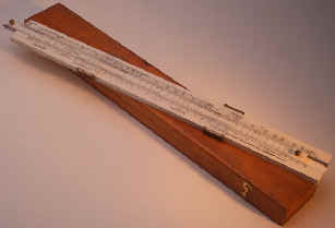
Pilot Balloon slide rules like this one were used by meteorologists in the weather services and military units of the United Kingdom to determine the upper wind velocities from an ascending hydrogen or helium filled Pilot Balloon (Note: use of helium was not common practice in the Met. Services if the UK) The position of the Pilot Balloon is tracked by means of one or two theodolites at one minute intervals. The Pilot Balloon slide rule is used to convert the observed azimuth and elevation readings into wind velocity and direction records. The use of slide rules and plotting boards was abandoned with the wide spread adoption of computers and programs to do the calculations, as well as the decline in the use of optical pilot balloon theodolites.
Since the angular co-ordinates of the balloon change bit little from one observation to the next, while the linear co-ordinates change considerably, it is advantageous to have the trigonometrical scales of the rule fixed and the linear scales movable. Two sine scales are required as the sine and cosine of the same angle must be indicated by cursors simultaneously. There must be three cursors at least to work on the trigonometrical scales and they must be made so that those on opposite sides of the rule may pass each other readily. These features were all introduced in the original pilot-balloon slide-rules made for the Meteorological Office in 1915. These rules were provided with double slides with which allowance could be made for variations in the assumed rate of ascent of the balloons. With the adoption of standard rates of ascent in the 1920's the extra slide became unnecessary and observers were instructed to lock the two slides together. When the use of the "tail method" to estimate the range to the balloon became more general practice the design of the slide-rule was modified to incorporate an additional pair of scales and a fourth cursor for the calculations involved in tail ascents. The "modified" pilot balloon slide rule was annotated Mark II.
Later models MK IV, MK IV.A, MK V and MK 5 had similar features, but omitted wood and glass in their construction. Plastic laminated frames and slides with Plexiglas cursors were used. Scales were similar to the MK II with additions and changes in fiducial marks as well as the MK V and MK 5 being of wider and thicker construction.
The Met. Office of the United Kingdom designated at least 6 different Pilot Balloon slide rule models. The first model in appearing 1915 made of wood by J.J. Hicks with two slides and introduction of the final, MK 5 model in the Late 1960's. Slide rules in this series starting with the MK II of 1927 have, 4 captive cursors (Glass or Plexiglas windows and brass guides) that ride in slots on the top and bottom edges. Each can be moved independently of one another. Brass knobs at both ends of the slide facilitate its movement. The rules are approximately 24.5" long.
| Pilot Balloon Slide Rules (Dates are estimated from known examples) | |||
| Mark I | 1915 to 1938 | J.J. Hicks | 2 Slides which are lockable and three cursers |
| Mark II | Pre 1928 to 1943+ | A.G. Thornton, W&G | W & G Units produced in Melbourne Australia differ slightly from Thornton rules. |
| Mark III | ? | A.G. Thornton Ltd. | Dates not known, similar to Mark II in appearance |
| Mark IV | 1952 to 1960 | James Farrow & Son | Some examples labeled Hilger and Watts have also been seen. |
| Mark IV.A | 1957 - 1964 | B.R.L | |
| Mark V | 1964-? | B.R.L & Blundell Harling Ltd. | Not Known if Mark V and 5 were in overlapping production. |
| Mark 5 | 1968-? | Blundell Harling Ltd. | |
Pilot Balloon slide rules are scarce, probably because relatively few were made, and also because most were made for and used by Government agencies, and not individuals.
Slide rules like these were not used in the United States Military or Weather Services. Wind speeds and directions were solved utilizing a Plotting Board. A standard slide rule or a slightly modified 20 inch trig rule was utilized along with the plotting board. Since the speed and direction information was solved on the plotting board and the slide rule was only used for determining the horizontal distance from the observer (a trig function).
Acknowledgements: Thanks to Mr. Colin Barnes for assistance with historical information. See also M.O. 577, Handbook of Meteorological Instruments Part II pg. 34 (1961, Her Majesty's Stationery Office)